On The Bench @ W5USJ
A Compact SA-612 and LM-386-4 Minimal Receiver For 10 MHz WWV and Amateur 30 Meters
Uses a 10 MHz crystal for WWV and various 30 meter crystals for CW and Digital Reception
Refer to the schematic at the bottom of this page for details.
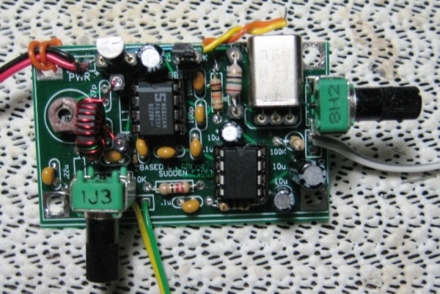
Pots are attached for bench testing...
WWV+ Project 10MHz Receiver Development Images — Support Images PDF Drawing
I started this project in the winter of 2016/2017 taking another look back at the MRX-40 in QST September 1997.
Prior to this I had built the MRX-40 with PCBs from Fred's but wasn't satisfied with the results. So I set it aside.
For few years in the mean time, I'd been working with Rex and his various versions of
the QRPme Sudden Storm receivers and other development projects.
That led me to creating prototype artwork for a version of a WWV receiver with ExpressPCB. Worked out OK and
quite well, if I must say so myself. Rex helped me get some PCBs based on the ExPCB layout and and I built my first
7 MHz fits-in-a-mint-tin receiver: it worked too. 8^) The ExPCB artwork is shown on the images page.
Recent activity with 10MHz WWV receivers started me working on an updated 10 MHz version, circuit and PC board.
The results are described in these pages...
PURPOSE:
• The purpose of this project is to develop a small 10 MHz Rx for WWV-10 and the Amateur 30m band.
• Reviewed several RX versions: the original GQRP Sudden Rx by Rev Dobbs, the GQRP 30m Rx kit, QRPme Sudden Storms,
KD1JV WWV only, K7QO 4 MHz Rx experiment and the original MRX-40.
Front end input circuits considered included tapped capacitor, link coupled single-tuned and two bandpass filter designs.
Link-coupled single tuned was selected. The tapped capacitor versions, MRX-40 and Sudden Storm, are detuned by the attenuator pot,
GQRP uses the 5u3L 10mm cans for the BPF.
They take too much realestate and also have a 1-2dB ripple in the pass band. A coil and capacitor version of the BPF was built and tested
good but also too much PCB space. Pictures and Spice models are included in the attached documents. A partial schematic of the component
BPF is included on the schematic below.
• Also considered a couple of LM-386-4 amplifier circuts such the basic version shown in the data sheets and an
ultra high gain version, up to 70 dB, from JF1OZL. I didn't use the 70dB version for my project, too many parts,
but did use it for a QRPme WWVR 10 and 5 MHz RX buildathon kit. The basic circuit is included FYI on the schematic below.
Project Notes:
• Component values for the input circuit can be peaked for WWV or 30 meters. As shown by the curves on the images page,
tuning is broad enough to cover 8.8 to 11.4 MHz within about -1 dB. (approximated from a spice model)
• Tuning range using the BB910 varactor was adjusted to tune above and below the crystal marked frequency.
• With a 10Vdc supply voltage and a 15 uH series inductor, some example ranges (rounded):
10 MHz; 9.995-10.005
10.116; 10.107-10.124 (most CW signals heard in this range)
10.140; 10.134-10.142 (many digital signals heard)
10.006; 9.995-10.005 (just for info)(L1-18uH better range for this frequency)
From a selection of crystals on hand. Differences in components and supply voltage effects the ranges.
BB910 Capacitance range is about 60 to 15 pF, 0.1 Vdc to 10 Vdc.
• At 10 MHz using a Butternut antenna, and propagation conditions, signal strength varied from marginal to S9.
With the signal tuned to zero beat, the announced audio was intelligible. A demodulator could be added requiring additional PCB space.
Signal strength was adequate throughout most days (some attenuator use at times) to drive a small 8 Ohm speaker.
• Signal generator measurements:
• At 10 MHz an RF input level of 0.001 Vpp and a 7.5 Ohm resistive load, produced an audio power output of ~67 mW at ~1 kHz.
2 Vpp = 1 Vp, 1 Vp x .707 = .707 Vrms, .707 ^2 = .5 / 7.5 = 0.067 W
Doesn't sound like much: it's quite loud with an 8 Ohm speaker.
• I would summarize that the project was successful meeting the objectives and maybe a little more...8^)
• Note: When I get a 5 MHz crystal, I'll modify and test a receiver for the 5 MHz WWV frequency.
Fun Stuff...
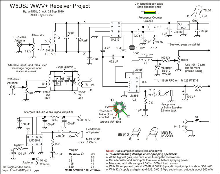
WWV 10MHz 30m Receiver Schematic: Drawn using Canvas-12; Software I've used for illustrating since v 2.5
W5USJ at 9plus dot NET
© CyM-TEC 2019 Forward