Heres a couple of my favorite special antenna projects. The quad parts were published as an article
with sidebar by W4RNL in the AntennaX online magazine. I really liked the results obtained with the
helix antennas. Too bad AO-40 didnt stay operational long enough for me to get on the air with them.
Back to Contents
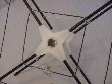
| UHMW Spreader Supports | The model shown here illustrates the use of the UHMW plastic as spreader supports. The spreaders are fiberglass kite spars. The center elements are an acutal 2-element 70cm quad with a gamma match. |
 |
 |
This quad was built from W4RNLs web site info. Shown here in use for satellite operation 2m up and 70 cm down.
Does a good job for transmit and receive. A bead balun choke is used to balance the feed point on transmit. |
| Support Drawings |  |
|
| Note: My use of a wire wrap to hold V/UHF quad elements in place was originally intended for experimentation. Quads could be easily assembled and disassembled. It has worked out and holds up so well in use that it has become standard practice. I use a 6-inch length and fold it into a U over the spreader arm. The U is placed under the spreader behind the element. It is then wrapped over the element and back under the spreader where it is twisted together. Extra wire is clipped off. Adhesive can be used to additionally secure the connection. See Large Block Drawings | ||
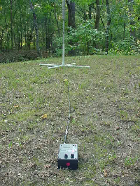
| HF6V Portable PVC Support | 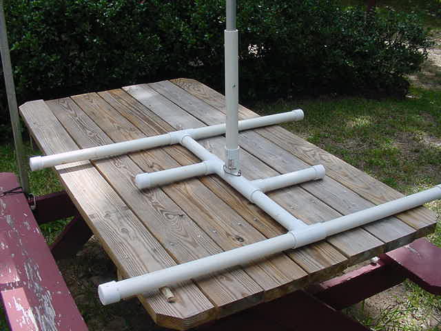 |
|
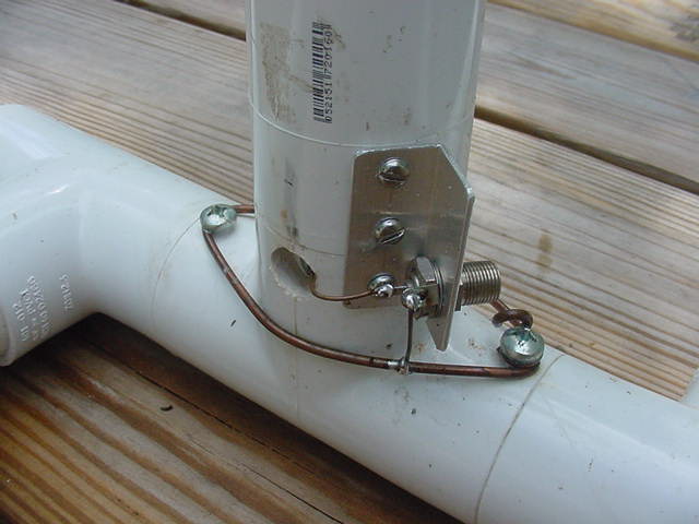
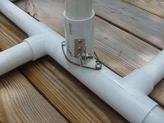
| The base section of the antennas is mounted in the 1.5 inch PVC pipe and fastened with two self-taping screws. A clearnce hole is drilled in the PVC and another at the antenna bottom for a #6 self-taping screw to fasten the RG-6 ¼ wave matching section. The type F connector is now mounted on a small angle bracket. RG-6 was the only 75 Ohm coax I had on hand to make the matching section. The antenna is disassembled at the first joint above the base and the first joint above the coil section. Quite transportable but backpacking might be a problem. See Large Base Closeup | ||
 |
|
|
| Radials are clipped on to the ground buss around the base. The ground for the feed line is soldered here too. The HF6V base coil wasn't installed but the antenna tuned up OK anyway with the 4 26ft radials used. Tuning was done according to Butternut instructions using an MFJ-259B analyzer. An 80 ft length of RG-8X was connected to the end of the matching setup and over to the FT-857 in my pickup. Note the 5-bead balun between the matching section and the analyzer. This was all finished up field day and I worked at least one station on each of the open bands (40, 20 and 15). See Large PVC Base and Coils (Old Base Version) | ||
| 13cm (2.4 GHz) Helical Antenna | One of a pair of 13 cm helicals built for the transmit array. Info from various websites provided the design basics. Note the single hole mounting using a 7/16 bolt into the tapped support. A combiner for the array was built from 1 in sq. and 5/16 dia. tubing. The mechanical assembly for the antenna is shown in the drawings below. | 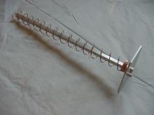 |
| Helical Feed Antenna | 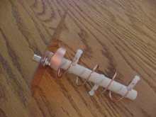 |
The 13 cm helix feeder shown here uses CPVC for the support. This works well for short helix antennas. The reflector is PCB. A matching section is made from thin copper such as that used by metal sculptors. Similar construction to build 16-turn helix antennas is shown in the other drawing below. These were built for use with AO-40 which is no longer operational. |
16-Turn Helix Antenna Support Drawing
5-Turn Helix Feed Antenna Support Drawing