HiMites are next-generation transceivers based on the Rock-Mite from SWL designed by Dave Benson, K1SWL.
The significant differences are VXO and RIT a transformer coupled front end** and a beefed-up transmitter.
The kits are available in versions for 20, 17, 15, 12 and 10 meters. A general schematic of the HiMites is shown below.
My version of a dual-crystal band pass filter is also shown below. This filter eliminated most all SWBCI in my HiMite-15 and -20.
** To minimize SWBCI in the HiMites, Dave has redesigned the receiver front end with a dual-crystal bandpass filter.
Back to Contents
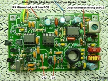
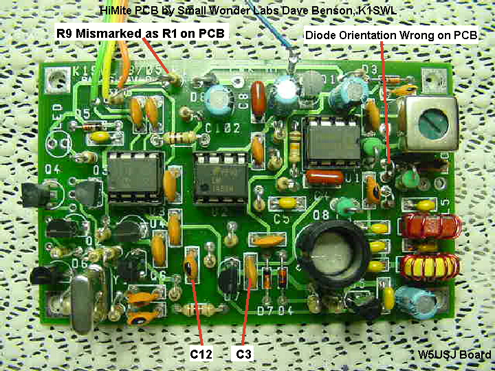
| HiMite PCB Markings | The original boards (03/05) have some incorrect silk screening. They are shown on the picture. Be sure to correlate the parts
with the schematic to ensure correct placement.
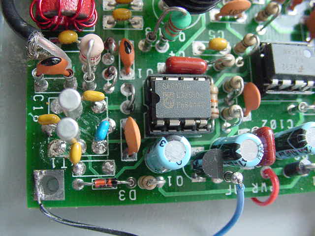
Large PCB Picture R1 top center is R9, C12 marking is next to C3 location. C12 is between R16 and R18. C3 is between Q7 and D7. C109 is not used. Diodes D1 and D2 orientation is marked incorrectly. |
 |
| HiMite PCB Stuffed |
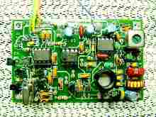 |
Hi Mite PCB stuffed and wires connected for the paddle jack, pushbutton and audio output. A pullup for the anticipated
RMK keyer chip is installed and shown below.
Machined DIP pins removed from IC sockets are used in key component locations. This makes it easy to experiment with mods and other enhancements. DIP pins used at part locations L1, L2, L3, L6, C18, Y1, R8, C8, Q6, R21 and AF. |
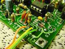
| Keyer Pullup Installed | Pullup resistor for the RMK keyer chip from Jackson Harbor. The resistor is mounted in the hole for the pushbutton lead.
Solder in position with about 1/4 inch of lead above the board for connection of the pushbutton lead (U1 Pin 4). The other end of the pullup
is bent over and soldered to the top of the adjacent R9* resistor. Note that this works equally well for the PicoKeyerRM chip.
*Mismarked R1 on this early PCB version. |
 |
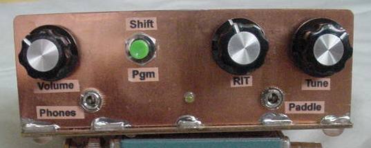
| HM-15 in an LMB CR-442 Enclosure | 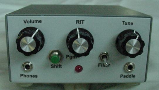 |
Heres the front of the HiMite-15 enclosure. Controls are Volume, RIT, Tune (VXO), Shift/Program Pushbutton and Audio Filter In/Out. Also the Headphone Jack, RIT/Shift LED and Paddle Jack. Power connector, power switch and BNC antenna jack are on the back panel. |
| I paint most of my boxes with a medium gray color I like. The LMB Crown Royal series enclosure used here is CR-442 and is Mouser part number 537-CR-442. The supplied color combination is light blue and gray. The light blue half is painted medium gray. | ||
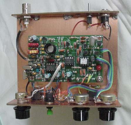
| HM-15 Inside View | The HiMite PCB is mounted centered with two 1/4 inch plastic spacers. They are at the lower left and upper right corner positions. The other two mounting locations are used as ground connections. One for the power ground and the other for the paddle jack, headphone/audio jack and the pushbutton ground connection. The KD1JV audio filter will be mounted as shown in the picture below. | 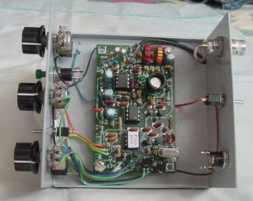 |
| Crystal Ground | 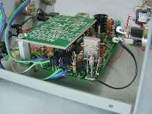 |
The crystal ground clip is cut from the small end of a paper clip. The clip is soldered to a ground point with a flexible lead. The KD1JV audio filter board is shown mounted on a standoff and is in place to check for interference. All OK! |
| HiMite-15 Z-Match |
Single-band Z-Match built specifically for the HiMite-15. The enclosure is an LMB CR-321, Mouser PN 537-CR-321. Capacitors are 220 pF total similar to those used in the BLT. Coil is wound on a T68-6 with 16 turns #22. Links are 10 turns Hi-z and 4 turns Lo-z. The visual SWR indicator is similar to that used in the BLT. | 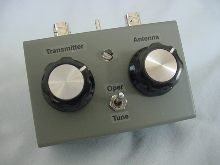 |
| Z-Match Inside | 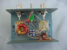 |
Inside view of the HM-15 Z-Match showing component location. The circuit is taken from ARRL Antenna Compendium #5
and is essentially the same as the circuit for the NorCal BLT. The BLT is now being sold by Hendricks Kits, qrpkits.com.
See the 15 meter z-match schematic below. Note: the tuner will match my antennas from 15 to 6 meters |
| HiMite-20 PCB Frame |
 |
|
| The HiMite-20 is mounted in a PCB frame made for Radio Shack double-sided PCB. Using this method allows easy access
to the unit for experiments and mods. Machined DIP pins are used at key component locations. Part values and types are easily
changed and measurements made of the results. Emitter resistor R21 is changed to 2 Ohms. The series output circuit, 2.2uH/27pF, is
removed and replaced with jumpers. A 27pF capacitor is connected acrossed L5. Also you can see the receiver input transformer is replaced with
a 2-crystal filter. The filter is similar to that shown in the photo below of the HiMite-15, only with HC-49 crystals rather than the cylindricals.
Both work OK. Click here for a larger view. HiMite-20 Inside |
||
HiMite-15 Schematic
KD1JV RM Audio Filter Schematic
15 Meter Z-Match Schematic
HiMite-15 2-Crystal Filter Modification SWBCI Reduction
HiMite-15/20 2-Crystal BP Filter