Tx/Tuna Toppers are kitted by QRPme.com
All Documentation for Topper kits is available on the QRPme.com website
The Current Kit is Ver.5 Dated 11/15
Tx Topper Ver.5
Historical Development Background and Information
Update 17aug13: More power output, less RF drive, lower supply voltage with FET bias voltage change.
Tx/Tuna Topper Evolution
TxTopper QRP Amplifier Assembly Using DIY PCB No. 1
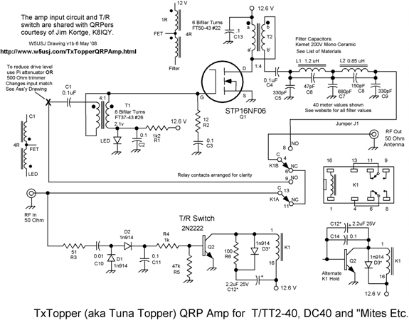
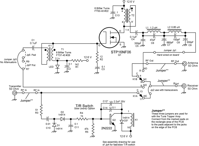
TxTopper QRP Amp Original Schematic TxTopper QRP Amp Blue Board Schematic Note ID Change for C9 All Rights Reserved 2008-2011 Chuck Carpenter, W5USJ — Rev 23Feb2011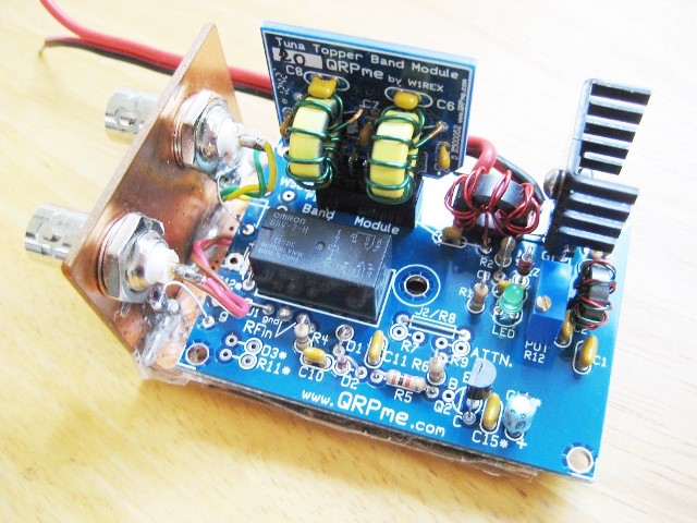
TX Topper 5 Watt + Amplifier with Adjustable Gate Bias Shown in Test Fixture
Recent testing with batches of FETs, (Q1) indicates that raising the gate
bias voltage can provide significant benefits.
Caution!
ENSURE that LED lights before installing FETs. Otherwise, the FETs will smoke when power is applied.
Change LED to 2.7V ultrabright green or possibly 3.3V ultrabright blue LEDs. Alternately connect a 1N5711 or
1N4148/1N914 in series with the 2.0V green LED. Requires a trace-cut to patch the diode into the circuit.
Five Watt QRP Amplifier de W5USJ
A Compact Basic Design For 160, 80, 40, 30 and 20 Meters — No Bells or Whistles
Wayne McFee, NB6M's, Mini-Boots Amp was the inspiration for the TxTopper project.
Tx Topper reference information follows
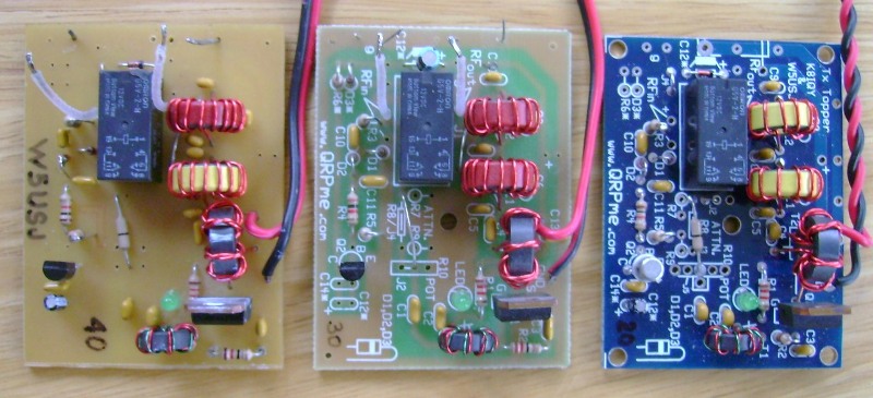
Left to right: Original development — 1st QRPme.com kit board — 1st blue kit board
(Heat sinks left off for clarity)
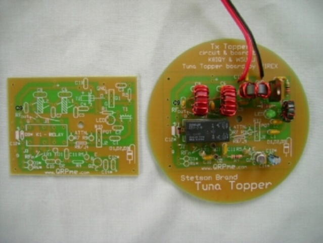
Note that the Tx Topper kit boards are cut from the round Tuna Topper boards
TX/Tuna Topper User Guide (2MB) —
Tx/Tuna Topper User Guide
Blue Tx/Tuna Topper PCB
"Blue" PCB Revision Notes PDF here —
Tx/Tuna Topper Revision Notes
"Blue" PCB T/R Jumpers and Switch Speed Info —
T/R Jumpers and Speed Info
Refer also to the revised blue board PCB schematic below.
The prototypes of version 1 were sent to Jim Kortge, K8IQY, for testing and evaluation
Results were less than encouraging. Jim did some modeling and suggested circuit changes
The changes were incorporated and provided significantly better results
Download Comparison PDF here —
TxTopper Comparison PDF
Revised Measurements for 40m and 20m Prototypes
12.6 Volt Bench Supply, Switched Attenuator, O'Scope and Welz 50 Ohm Dummy Load
DC40A, RM/40 and DC20A RF input sources (All using 12.6V supply)
DC40 @ 13V p-p in = 46V p-p output — Approx. 420mW in for 5.25W out
DC20 @ 17V p-p in = 47V p-p output — Approx. 720mW in for 5.5W out
RM/40 @ 12V p-p in = 42V p-p output — Approx. 360mW in for 4.4W out
Note that with 13.8V at the board, key-down, less drive power is needed for 5W output.
Heatsink - Using ones salvaged from UPS PCBs.
Appears to be Mouser # 567-270-AB
70degC @4W natural conv.
Doesn't take much heat sink. Operated into the dummy load for 3 hours in beacon mode
Heatsink only warm to touch. One made from a 1-1/2 length of 3/4 aluminum angle works OK too.
Note: The heatsink on the DC40A was hotter than the one on the TxTopper.
Stress Test 17May'08, Beacon Mode to dummy load, 8.5 Hrs, 6Watts Output, No Problems!
Ready to install into an enclosure
Initial test produced the same results as described above using the DC40A.
See Assembly PDF for PCB Component Layout Drawing (Photo positive artwork 2x/1x PDF Also Available)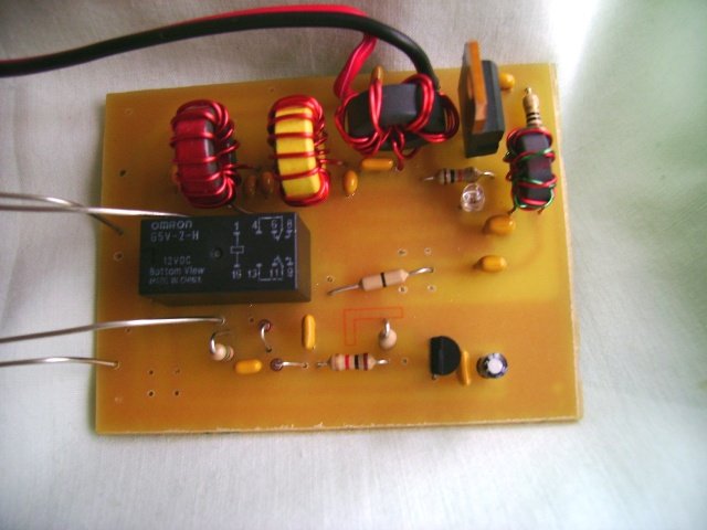
TxTopper Assembly
The first PCB etched right here at the W5USJ QTH. Board size 2 x 2.6 inches.
PCB is made using sensitized paper phenolic that is easier to cut than epoxy glass.
Artwork was produced using graphics software and printed on a transparency with an
inkjet printer. Not recommended but worked OK. An MG Photofabrication kit from Circuit
specialists was used to produce the PCB. Resist does not need to be removed. You can solder
through it and leaving it protects the copper.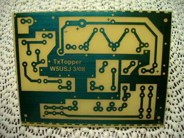
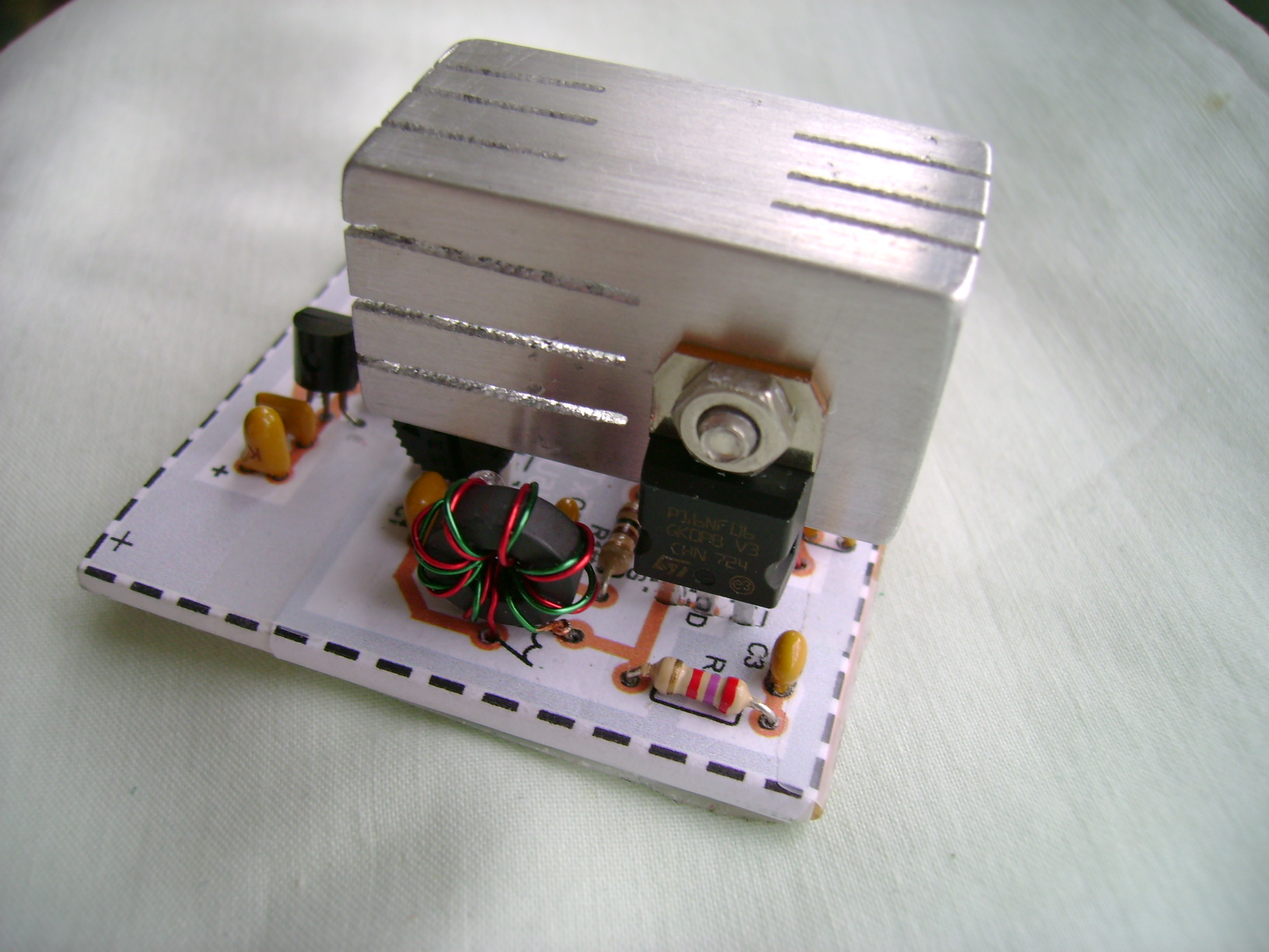
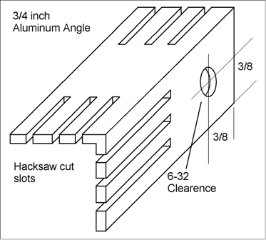
The heatsink is made from a 1-1/2 inch length of 3/4 inch aluminum angle. The dimensions are not critical
but need to clear the components and the sides of the enclosure. Use heatsink compound between the FET and heatsink
for best heat transfer. Beacon mode, 3 hours, 3x2 CQ 3second pause repeat.
Picture of "Original" QRPme.com Tx/Tuna Topper —
Tx/Tuna Topper PCBs
Download Schematic PDF here —
TxTopper Schematic PDF
Download Blue Board Schematic PDF here —
TxTopper Blue Board Schematic PDF
Download "original" PCB Assembly Instructions here —
TxTopper Assembly Instructions PDF
Download PCB Assembly Drawing here —
TxTopper Assembly Drawing PDF
Download PCB 2x/1x Positive Artwork here —
TxTopper Positive Artwork PDF
Download Bifilar Toroid Drawing here —
TxTopper Bifilar Toroid Drawing PDF
Download TxTopper LOM PDF here —
TxTopper LOM PDF
Download Separate Receiver T/R Mod drawing here —
'Topper T/R Mod Dwg
Mechanical peripherals parts can be the builders choice.