Surface mount version of the QRPme TTT2
PK-DC Surface Mount Keyer
Surface Mount MRX-40 Receiver
Surface Mount T/R Switch
Surface mount "classic" RF Probe
© 2009 Chuck Carpenter, W5USJ — Rev 18Apr09
Revisions and Updates since the pictures were taken —
Revision and Update Notes
Back to Contents
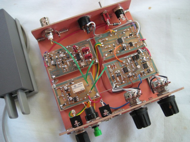
Simple Circuits Converted to Surface Mount Construction
The SMT Project includes a version of the QRPme Two Tin Tuna (TTT2) transmitter, PK-DC Keyer
MRX-40 Receiver, T/R Switch de TxTopper and an RF Probe
Only the RF probe is available as a simple surface mount kit
View/Download SMT 4-Component Transceiver Interconnect PDF Here —
4-Component Transceiver
View/Download Surface Mount Assembly Notes PDF Here (321k) —
Surface Mount Assembly Notes
View/Download List of SMT Materials PDF Here —
Surface Mount List of Materials
View/Download Combined Contact Artwork for all 5 PCBs —
Combined Artwork Drawing PDF
View/Download SMT System Block Diagram PDF —
SMT System Block Diagram PDF
Circuit boards are produced with MG Chemicals Photofabrication Kit methods, materials and procedures
(e.g., 416-k available from Circuit Specialists)
PCB material is mostly single-side 1/16th paper phenolic or 1/32 single-side FR-4
Paper phenolic is easy to cut with a sharp scribe and straight edge, thin FR-4 cuts with tin snips
Finished PCB size is ~2.7cm x 4.8cm
Camera distortion not included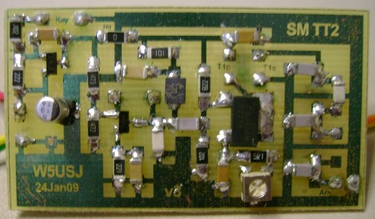
The crystal, output transformer and filter coils are now on the front side
PCBs are made using pre-sensitized 1/32 FR-4 (or 1/16th paper phenolic) that's easier for me to cut than 1/16th FR-4
Note: Resist can be damaged by cutting before etching. Score the cut line with a sharp knife first
One Change: For etching I use a mixture of 2 parts hydrogen peroxide and 1 part muriatic acid.
The solution is clear and you can see the etching process. I heated the etch tray with a hair dryer.
Wear eye protection and use in a well ventilated area.
Artwork was produced using graphics software and printed on transparencies with an
HP cp1700 inkjet printer using highest quality settings. Not recommended but worked OK.
Resist does not need to be removed. You can solder through it and leaving it helps protect the copper.
Immersion Tim Plating (ITP) would provide a better looking PCB. Kepro provides a product to do this.
View/Download TTT2 Schematic PDF —
TTT2 SMT Schematic PDF
View/Download TTT2 PCB Assembly/Artwork —
TTT2 Assembly/Artwork Drawing PDF
Using the PK-DC keyer chip from Jackson Harbor
Finished PCB size is ~2.7cm x 4.8cm
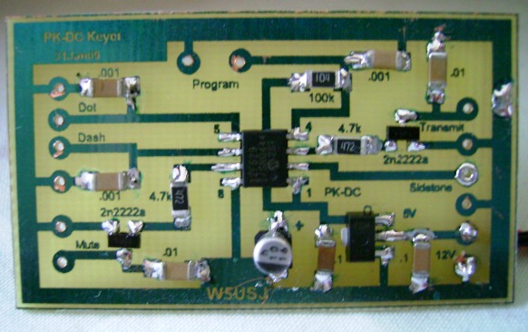
Surface mount keyer using the Jackson Harbor PK-DC SM keyer chip as the engine
Lots of space between parts to make assembly easier
A compact keyer that will run for more than a year on a 9V battery and a package not much larger than the battery
Features and functions are similar to the NorCal keyer and the RMK keyer for the Rock-Mites
Includes timing for T/R switching (See schematic)
One special difference is the Tune Mode accessible via menus or the 5-didah mode, toggles with paddle
For a complete description of the PK-DC Keyer features and functions, go the Jackson Harbor site, PK-DC
Jackson Harbor Keyers
View/Download PK-DC Keyer Menu Summary PDF —
PK-DC Keyer Menus PDF
View/Download PK-DC Keyer Schematic PDF —
PK-DC Keyer Schematic PDF
View/Download PK-DC Keyer PCB Assembly/Artwork —
PK-DC Keyer Assembly/Artwork Drawing PDF
Finished PCB size is ~2.7cm x 4.8cm
SMT MRX-40 Receiver Assembly
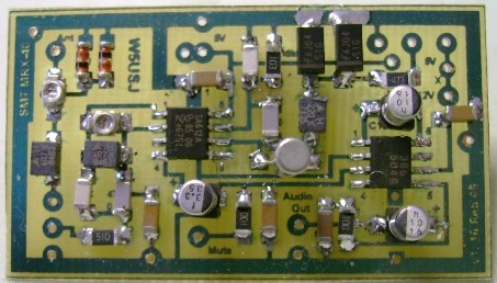
Surface Mount parts version of the "Classic" MRX-40 receiver as described in QST and other publications
Other versions of the MRX-40 receiver are the NorCal SMK-1 kit, the QRPme Sudden Storm and
the version found in QST. Far Circuits has an etched PCB for the QST version.
Mods made to the SMT version of the basic original circuit with a little help from W1FB's QRP Notebook
View/Download SMT MRX-40 Schematic PDF —
SMT MRX-40 Schematic PDF
View/Download SMT MRX-40 PCB Assembly/Artwork —
MRX-40 Assembly/Artwork Drawing PDF
Finished PCB size is ~2.7cm x 3.5cm
SMT T/R Switch Assembly — PCB slightly over etched but quite useable
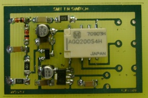
Surface mount T/R switch for use with seperate transmitter and receiver
The switch is RF activated and can be used with the SMT PK-DC Keyer to control T/R operation
View/Download T/R Switch Schematic PDF —
T/R Switch Schematic PDF
View/Download PK-DC Keyer PCB Assembly/Artwork —
T/R Switch Assembly/Artwork Drawing PDF
Finished PCB size is ~8mm x 30mm
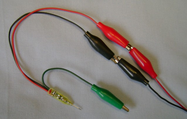
The board has through-hole pads for soldering leads or attaching a 3-pin header with 0.1 spacing
The header pin is used to provide a sharp probe that doesn't slip off the contact point
At QRP RF levels a shield isn't needed. The assembly can be enclosed in a heat shrink tube for
support, protection and strain relief for the leads. If needed, the width of the board can be trimmed
about 1.5mm each side to fit inside a tube like a plastic pen; be creative.
Note: — the boards are easily trimmed when etched on 1/32 FR-4 PCB material
Also, be sure to remove the outline trace all around the edges and between the output pads
View or Download RF Probe PCB Assembly/Artwork —
RFP Assembly/Artwork Drawing PDF
Link to QRPme.com SMT RF Probe Kit Info Sheet PDF —
QRPme AssemblyDrawing PDF